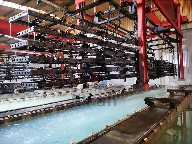
Why do some metal parts come out of the tank looking perfect on the outside but stay completely bare in the corners? This is the Faraday Cage effect. In the electrophoretic coating process, electricity takes the easiest path. It hits the exterior surfaces first and creates a shield that blocks the paint from reaching deep recesses, tubes, or sharp internal angles.
If you don’t fix this, you end up with “dead zones” where the metal has zero protection. These thin spots are the first places where rust starts. For any manufacturer, uneven film thickness means your product might fail salt spray tests or rust out in the field far sooner than it should. Understanding how to break this electrical shield is the only way to ensure 100% coverage on complex geometries.
Why Does the Faraday Cage Effect Occur During Electrophoretic Coating?
To fix the problem, you first need to understand the physics behind it. Electricity is lazy. During the electrophoretic coating process, the electrical current always seeks the path of least resistance.
The Physics of Electrical Shielding
When you submerge a part in the tank, the electrical field lines rush toward the nearest conductive surface. These lines “clump” together on exterior edges and flat outer faces. Because the outer surfaces absorb the current so quickly, they create an electrostatic shield. This shield pushes the remaining field lines away from the interior, preventing the paint particles from ever reaching the deep recesses or sharp internal corners.
Voltage vs. Shielding
Many operators try to solve the issue by simply turning up the voltage. However, this often makes the problem worse. High voltage increases the deposition rate on the outside too fast. The outer film builds up and becomes a resistive barrier before the paint has a chance to “crawl” into the holes. This gap between the coated exterior and the bare interior is the heart of the Faraday shield.
Identifying “Problem Geometry”
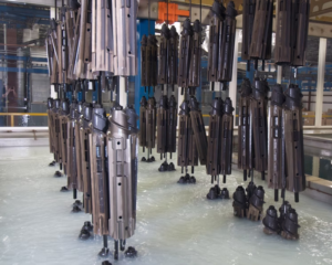
Some parts are naturally harder to coat. If your electrophoretic coating line handles any of the following, you will likely face this challenge:
- Deep, narrow boxes or “pockets.”
- Long, hollow tubes or pipes.
- Intricate welded assemblies with overlapping metal layers.
- Sharp 90-degree internal angles.
Recognizing these shapes early helps you decide when you need more than just standard tank settings to get the job done.
Optimizing E-coat Tank Chemistry to Overcome Shielding
If the physics of the part design works against you, your bath chemistry must work harder. You can “force” the paint into difficult areas by adjusting how the liquid behaves. The goal is to increase the throwing power of your electrophoretic coating.
Maximizing Throwing Power
Throwing power is the ability of the paint to reach shielded areas. To improve this, you need to slow down the coating process on the outside so the current has time to move inward. High-quality electrophoretic coating products are designed with specific resins that allow the paint to “wrap” around edges more effectively. If your throwing power is low, the paint will only stick to what it “sees” first.
Conductivity Management
Conductivity is your most important lever. Think of it as the “fuel” for the electrical current. If the bath conductivity is too low, the current won’t have the strength to push through the resistive barrier of the Faraday cage. By keeping your conductivity and pH levels within a tight, optimal range, you ensure the ions can carry the paint particles into the deepest “dead zones.” However, you must be careful; too much conductivity can lead to film ruptures or pinholes.
Variables for Flow
Temperature and solvent content also play huge roles. A warmer bath usually improves the flow of the paint, helping it wet the surface inside tight corners before it hardens. Similarly, fine-tuning the solvent levels can keep the paint film “wet” and conductive for a few extra seconds. This small window of time is often enough to let the electrophoretic coating penetrate deep cavities that would otherwise remain bare.
Mechanical and Electrical Solutions for Your Electrophoretic Coating Line
When chemistry alone isn’t enough, you must change the physical and electrical environment inside the tank. These mechanical upgrades are often the only way to guarantee coverage on the most complex industrial parts.
Auxiliary Anodes (The “Golden Rule”)
The most effective way to beat the Faraday Cage is to put the power where you need it. Auxiliary anodes, often called “slave anodes,” are small, portable electrodes that you place inside the hollow or recessed areas of your workpiece. By bringing the anode closer to the inner surface, you shorten the electrical path. This forces the electrophoretic coating to deposit exactly where the primary anodes cannot reach.
Pulse Rectifiers
Standard Direct Current (DC) sometimes creates a barrier too quickly. Many modern electrophoretic coating lines now use pulse rectifiers. Instead of a steady stream of power, these machines send electricity in rapid “bursts.” These pulses help break through the electrostatic shield and allow the paint particles to settle more deeply into corners before the outer film becomes too resistive. It is a high-tech way to “shake” the paint into place.
Jig & Rack Design
Sometimes, the solution is as simple as how you hang the part. If parts are too close together on the rack, they shield each other, making the Faraday effect even worse. You should design your jigs to tilt the parts at an angle. This prevents air pockets from forming and ensures that the electrical field lines have a clear “line of sight” to the interior openings. Proper spacing and orientation are the cheapest and fastest ways to improve your electrophoretic coating results.