A metal part comes out of the dip tank, but one corner remains bare. Another part has a complete coating on the outside, yet the inside of a deep cavity shows exposed metal. These defects can be frustrating because the rest of the surface may look perfectly normal. When electrophoretic coating leaves bare spots, the problem often comes down to three things: the coating bath cannot reach the surface, the electrical field cannot support deposition, or the metal surface is not ready for coating. Finding the cause requires looking at the part design and the process together.
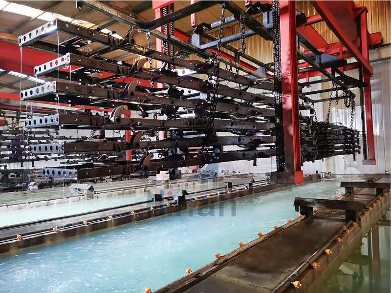
Poor Electrical Contact on the Hanging Rack
Electrophoretic coating relies on an electrical circuit.
The workpiece connects to the rectifier through its hanger or rack, while the counter-electrodes complete the circuit through the bath.
If the contact point has rust, paint buildup, or loose connections, current may not reach the part properly. As a result, some areas may receive little or no coating.
Start by checking the contact points on the rack. Look for worn hooks, loose clamps, and insulating deposits. Also, confirm that the workpiece makes firm metal-to-metal contact with the hanger.
If bare spots appear on several parts mounted on the same rack, inspect the rack and electrical connections first. If the defect affects only one part, check its individual contact point and position.
Can Trapped Air Cause Bare Spots?
Yes. Air pockets can prevent the coating liquid from contacting the metal surface.
This problem often occurs on hollow tubes, deep recesses, folded panels, and parts with upward-facing cavities. When a part enters the tank, air may remain trapped inside these features. The liquid cannot fully displace it, so the exposed metal never enters the normal deposition process.
The Electrocoat Association identifies drainage and air-pocket prevention as important design considerations for electrocoating. Poor part orientation can create air pockets during immersion and interfere with coating coverage.
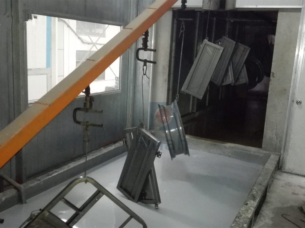
To reduce this risk, review the hanging angle and immersion direction. Allow trapped air to escape as the part enters the bath. At the same time, make sure liquid can drain freely when the part leaves the tank.
For new workpieces, consider these points during the design stage. Small changes to part orientation or rack design may improve coverage without changing the coating settings.
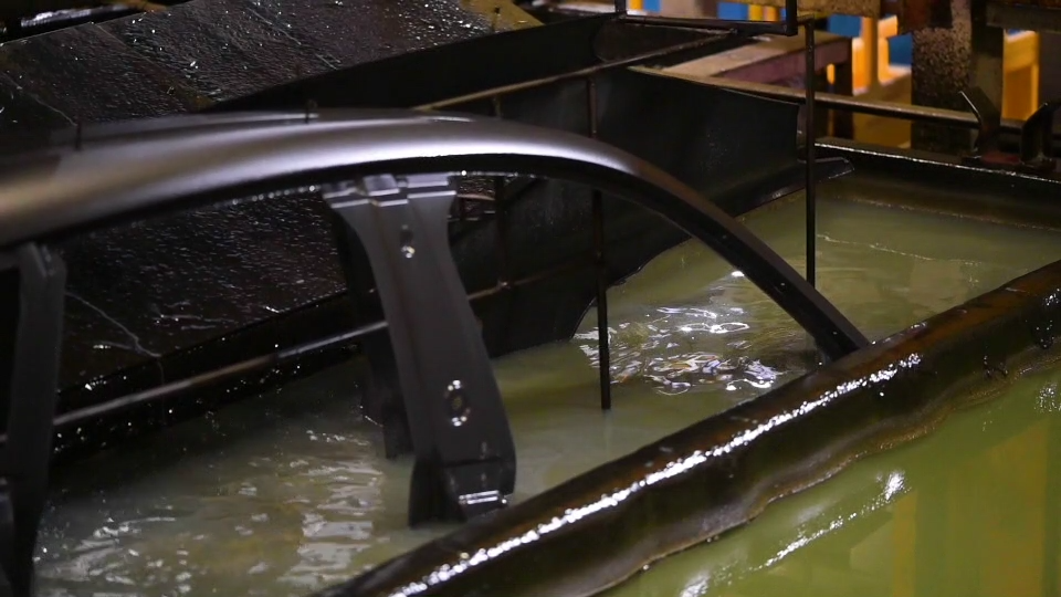
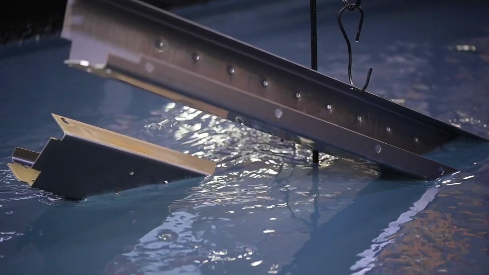
Does Part Geometry Limit Electrophoretic Coating?
It can.
Electrodeposition provides good coverage on many complex metal parts, but it cannot overcome every geometric limitation.
The U.S. Environmental Protection Agency explains that recessed surfaces may receive poor coating distribution when the electric field cannot reach them effectively. Very deep recesses can remain uncoated under certain conditions.
This is particularly relevant to narrow cavities, closely spaced components, and overlapping metal sections. The outer surfaces may receive sufficient current, while shielded areas receive much less.
Check whether the bare spots consistently appear in the same locations. If they do, the issue may relate to part geometry rather than a sudden change in bath conditions.
Possible solutions include adjusting the rack layout, changing the part angle, increasing clearance between adjacent parts, or reviewing whether the cavity design suits the process.
Inadequate Cleaning Before Electrophoretic Coating
Electrical contact and liquid access are not the only concerns.
The metal surface must also be clean enough to support proper film formation.
Oil, grease, drawing compounds, rust, and other residues can interfere with the coating process. Poor cleaning may leave isolated areas that resist uniform deposition or develop weak coating coverage.
Pretreatment usually includes cleaning, rinsing, and a suitable conversion treatment. Each stage prepares the surface for the next one.
If bare spots appear randomly across different parts, review the cleaning and pretreatment stages. Check cleaner concentration, operating temperature, spray or immersion coverage, and rinse quality. Also, inspect whether contamination has entered the process.
Do not assume that a normal-looking part has received adequate pretreatment. Some surface problems are difficult to identify by visual inspection alone.
Are Voltage and Bath Conditions Responsible?
They may be, especially when bare areas appear alongside other coating defects.
The rectifier supplies the voltage that drives deposition. However, simply increasing voltage will not solve every coverage problem. A shielded cavity or a part without reliable electrical contact may still fail to receive an adequate film.
Bath conditions also matter. Temperature, pH, conductivity, and solids concentration influence deposition behavior. The EPA identifies these as important parameters for controlling an electrocoating process.
Compare current readings and bath records with normal production data. Check whether the problem began after a voltage adjustment, bath replenishment, maintenance activity, or change in the workpiece mix.
Change one variable at a time, and follow the coating system’s approved operating range. This makes it easier to identify the actual cause.
How to Troubleshoot Bare Areas on an Electrophoretic Coating Line
A structured inspection helps prevent unnecessary adjustments.
- Map the defects. Record where bare spots appear and whether they affect one part, one rack, or the entire production run.
- Inspect the hanging system. Check electrical contact, rack cleanliness, and workpiece positioning.
- Review part geometry. Look for cavities that trap air, narrow gaps, or surfaces shielded from the electric field.
- Check pretreatment. Review cleaning conditions, rinsing, and conversion treatment.
- Verify the process data. Compare voltage, current, bath temperature, pH, conductivity, and solids concentration with established control limits.
This sequence helps separate a local mechanical or design problem from a broader process issue. Once the cause becomes clear, make a controlled adjustment and inspect the next production run.
Preventing Bare Spots in Electrophoretic Coating
Reliable electrophoretic coating starts before the part reaches the dip tank.
Clean metal, sound electrical connections, suitable part geometry, and correct hanging positions all contribute to complete coverage.
When bare spots appear, resist the urge to increase voltage immediately. First, identify where the defect occurs and check whether the coating liquid and electrical field can reach that area. Then review pretreatment and bath conditions.
A systematic approach helps engineers identify the source of poor coverage and maintain consistent results across an electrophoretic coating line.